
6kW 48V Off-Grid Cabin Solar Wiring Diagram PDF (6S2P)
Computed 6kW 48V cabin solar diagram: 6S2P array, wire gauges, OCPD, battery arrangement, routed parts and printable files.
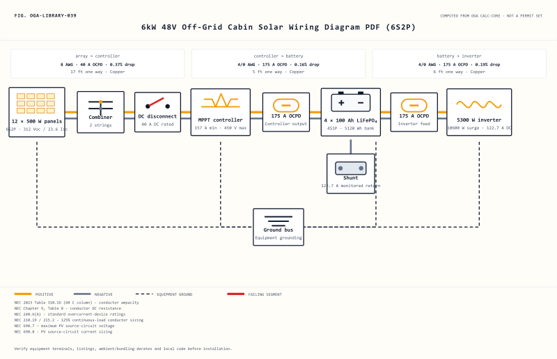
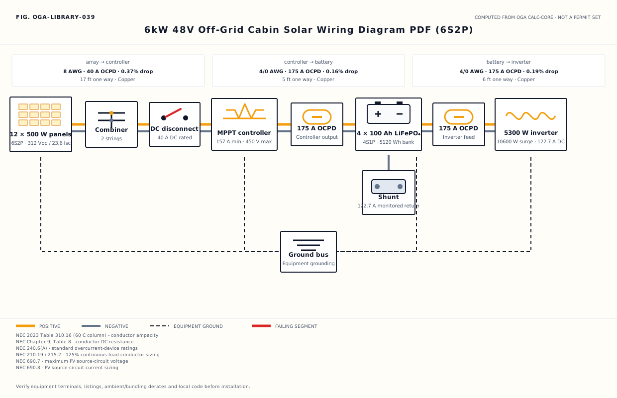
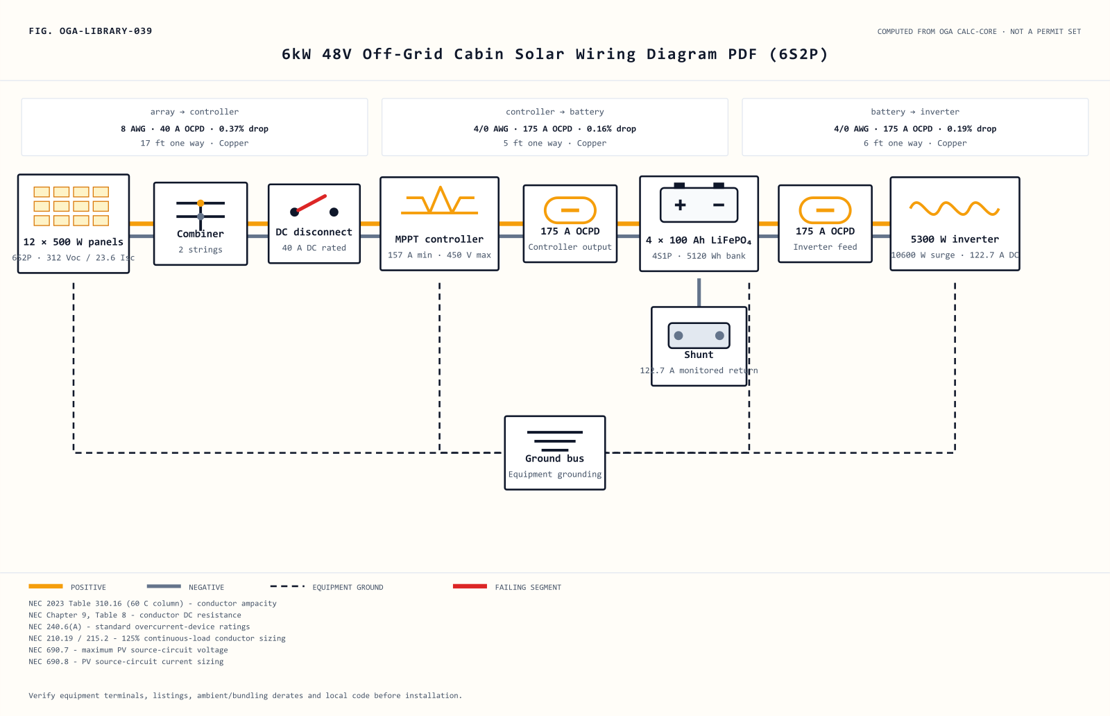
View the scalable diagram inline
What this computed plan shows
Numbers, not decorative lines, define the 6kW 48V Off-Grid Cabin Solar Wiring Diagram PDF (6S2P). The 6S2P field connects 12 panels for 6 kW of nameplate power, 264 operating volts and 23.6 short-circuit amps. That combination gives a cabin builder a concrete starting case that can be changed in the linked customizer.
A MPPT device is shown because the array and bank operate at different useful voltage points. The engine calculates 156.3 A of required controller output and tests 390 V against a 450 V input rating. These limits should be matched to a manufacturer datasheet, including its temperature assumptions.
The array-to-controller route is 17 ft one way and carries 36.8 design amps. It resolves to 8 AWG copper, a 40 A OCPD and 0.37% calculated drop. Downstream, the 5 ft controller lead uses 4/0 AWG copper behind 175 A protection, holding its computed drop to 0.16%.
The battery table translates 4 individual 100 Ah units into a 4S1P bank. In this 48 V design, the result is 100 Ah and 5,120 Wh of nominal storage. Usable energy will be lower and depends on chemistry limits, temperature, battery management and the connected load profile.
At the final DC segment, the current rises to 122.7 A for a 5,300 W inverter. The page assigns 4/0 AWG copper to the 6 ft route, with 175 A OCPD and 0.19% calculated drop. Termination ratings and the inverter maker’s fuse instructions remain controlling.
The generated SVG, PNG and tables intentionally repeat the same computed labels so discrepancies are visible during review. If a purchased controller, battery or inverter differs from the values above, regenerate the design from the linked machine before wiring. This cabin example is not a permit set and does not replace equipment instructions or a qualified local professional.
For later comparison, keep the 6 kW array, 4S1P bank and the 17/5/6 ft one-way routes together when requesting equipment quotes or an inspection review.
Wire, protection and battery schedules
Wire schedule
| Segment | Design current | One-way run | Computed conductor | Voltage drop | Sizing basis |
|---|---|---|---|---|---|
| array → controller | 36.8 A | 17 ft | 8 AWG copper | 0.37% | 156% of array Isc (NEC 690.8) |
| controller → battery | 125 A | 5 ft | 4/0 AWG copper | 0.16% | controller output at 125% continuous-load ampacity |
| battery → inverter | 122.7 A | 6 ft | 4/0 AWG copper | 0.19% | inverter continuous DC input at 90% efficiency and 125% ampacity |
Overcurrent protection
| Protected segment | Required ampacity | OCPD | Conductor ampacity | Verdict |
|---|---|---|---|---|
| array → controller | 36.8 A | 40 A | 40 A | within |
| controller → battery | 156.3 A | 175 A | 195 A | within |
| battery → inverter | 153.4 A | 175 A | 195 A | within |
Battery arrangement
| Arrangement | Chemistry | Units | Unit capacity | Bank capacity | Nominal energy | Nominal voltage |
|---|---|---|---|---|---|---|
| 4S1P | LiFePO₄ | 4 | 100 Ah | 100 Ah | 5,120 Wh | 48 V |
Static routed parts list
Parts are computed from this passing configuration. A route appears only when the verified catalogue record proves every displayed numeric rating; all uncertain matches stay local for verification. Routed links may earn Off Grid Authority a commission at no extra cost to you.
Pre-install review steps
- Confirm the array and controller window: Verify that the 6S2P string plan produces 312 V open circuit and that the equipment is rated above the 390 V cold-design value.
- Lay out the protected DC runs: Measure the one-way paths before ordering cable, then compare them with the computed 17 ft, 5 ft and 6 ft runs shown here.
- Build complete battery strings: Arrange all 4 battery units as 4S1P; do not leave a partial series string in a 48 V bank.
- Commission against equipment instructions: Check polarity, terminal torque, DC interrupt ratings, conductor temperature ratings, ambient correction and local inspection requirements before energizing the 5,300 W inverter.
Customize or compare
Open the parent build guide for the surrounding design context, safety notes and installation discussion.