
400W 12V Off-Grid Cabin Solar Wiring Diagram Complete (1S2P)
Computed 400W 12V cabin solar diagram: 1S2P array, wire gauges, OCPD, battery arrangement, routed parts and printable files.
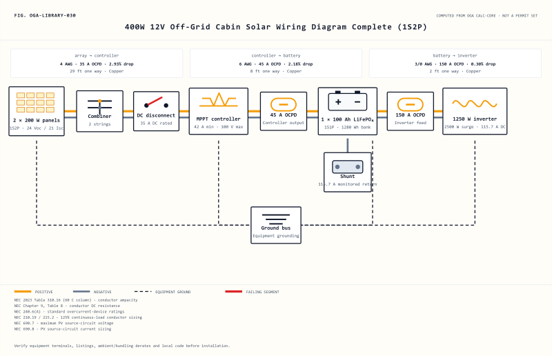
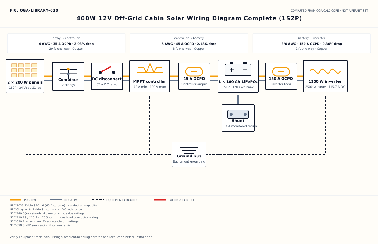
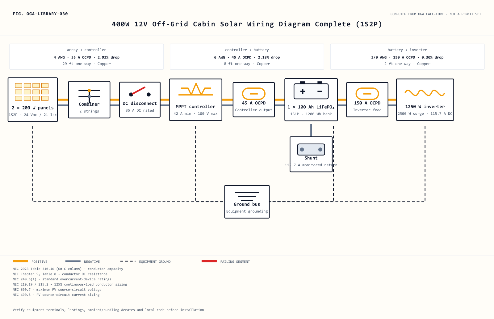
View the scalable diagram inline
What this computed plan shows
For the 400W 12V Off-Grid Cabin Solar Wiring Diagram Complete (1S2P), a 1S2P array gives 400 W of rated panel capacity for the cabin use case. Nameplate multiplication produces 24 Voc, 20 Vmp and 21 Isc at the combined array. Those values are carried forward into controller and conductor checks instead of being rounded into a one-size-fits-all diagram.
At the charge controller, the drawing records a 42 A minimum and a 30 V design Voc. Those are different questions: one protects adequate charging output, while the other keeps the 1S2P string below the equipment’s 100 V input limit. Both checks return within for this exact 400W 12V Off-Grid Cabin Solar Wiring Diagram Complete (1S2P) state.
Starting at the roof or rack, 4 AWG copper covers the 29 ft PV run with 2.93% drop and a 35 A protective device. The controller-to-bank segment is shorter at 8 ft, yet its 33.3 A design current calls for 6 AWG copper and 45 A OCPD. Distance and current are both visible because either can determine conductor size.
Storage is drawn as 1S1P: 1 LiFePO₄ units, each 100 Ah. That produces 100 Ah at 12 V and 1,280 Wh nominal. The complete-series-string rule is why the count and arrangement appear together rather than as an interchangeable battery total.
A 1,250 W continuous inverter draws about 115.7 A from this 12 V bank under the stated efficiency assumption. The 2 ft feed therefore becomes 3/0 AWG copper, protected at 150 A and calculated at 0.3% drop. Keeping this high-current run short is usually more effective than buying around a poor layout.
All three schedule rows pass the shared ampacity and voltage-drop checks for the inputs printed here. That does not account for every field condition, including conduit fill, grouped conductors, engine-room heat, corrosion exposure or manufacturer-specific terminal limits. Treat the 400W 12V Off-Grid Cabin Solar Wiring Diagram Complete (1S2P) as a traceable calculation snapshot and have work reviewed whenever the installation falls outside its displayed assumptions.
For later comparison, keep the 400 W array, 1S1P bank and the 29/8/2 ft one-way routes together when requesting equipment quotes or an inspection review.
Wire, protection and battery schedules
Wire schedule
| Segment | Design current | One-way run | Computed conductor | Voltage drop | Sizing basis |
|---|---|---|---|---|---|
| array → controller | 32.8 A | 29 ft | 4 AWG copper | 2.93% | 156% of array Isc (NEC 690.8) |
| controller → battery | 33.3 A | 8 ft | 6 AWG copper | 2.18% | controller output at 125% continuous-load ampacity |
| battery → inverter | 115.7 A | 2 ft | 3/0 AWG copper | 0.3% | inverter continuous DC input at 90% efficiency and 125% ampacity |
Overcurrent protection
| Protected segment | Required ampacity | OCPD | Conductor ampacity | Verdict |
|---|---|---|---|---|
| array → controller | 32.8 A | 35 A | 70 A | within |
| controller → battery | 41.7 A | 45 A | 55 A | within |
| battery → inverter | 144.7 A | 150 A | 165 A | within |
Battery arrangement
| Arrangement | Chemistry | Units | Unit capacity | Bank capacity | Nominal energy | Nominal voltage |
|---|---|---|---|---|---|---|
| 1S1P | LiFePO₄ | 1 | 100 Ah | 100 Ah | 1,280 Wh | 12 V |
Static routed parts list
Parts are computed from this passing configuration. A route appears only when the verified catalogue record proves every displayed numeric rating; all uncertain matches stay local for verification. Routed links may earn Off Grid Authority a commission at no extra cost to you.
Pre-install review steps
- Confirm the array and controller window: Verify that the 1S2P string plan produces 24 V open circuit and that the equipment is rated above the 30 V cold-design value.
- Lay out the protected DC runs: Measure the one-way paths before ordering cable, then compare them with the computed 29 ft, 8 ft and 2 ft runs shown here.
- Build complete battery strings: Arrange all 1 battery units as 1S1P; do not leave a partial series string in a 12 V bank.
- Commission against equipment instructions: Check polarity, terminal torque, DC interrupt ratings, conductor temperature ratings, ambient correction and local inspection requirements before energizing the 1,250 W inverter.
Customize or compare
Open the parent build guide for the surrounding design context, safety notes and installation discussion.